- 您现在的位置:买卖IC网 > Sheet目录17381 > ADP2102-1.5-EVALZ (Analog Devices Inc)BOARD EVAL FOR ADP2102-1.5
ADP2102
As a result of this auto mode control technique, losses are
minimized at light loads, improving system efficiency.
The PSM reverse current comparator controls the entry and exit
into forced continuous conduction mode. Some minor jitter is
normal during transition from DCM to CCM with loads at
approximately 100 mA typical, and it has no adverse impact on
regulation.
SYNCHRONOUS RECTIFICATION
When the load current is further increased such that the lower
peak is above the current limit threshold, the off time is lengthened
to allow the current to decrease to this threshold before the next
on-time begins.
Both V OUT and the switching frequency are reduced as the circuit
operates in constant current mode. The load current (I OCL ) under
these conditions is equal to the current limit threshold plus half
In addition to the P-channel MOSFET switch, the ADP2102
includes an integrated N-channel MOSFET synchronous recti-
fier. The synchronous rectifier improves efficiency, especially
at low output voltages, and reduces cost and board space by
eliminating the need for an external rectifier.
I OCL = I VALLEY + Δ I L /2
DC CURRENT LIMIT = MAX LOAD
(5)
CURRENT LIMIT
The current limit circuit employs a valley current sensing scheme.
Current limit detection occurs during the off time through
sensing of the voltage drop across the on resistance of the
synchronous rectifier switch. The detection threshold is 1 A
typical.
INDUCTOR
CURRENT
I OCL
VALLEY CURRENT LIMIT
Figure 44. Valley Current Limit
TIME
Δ I
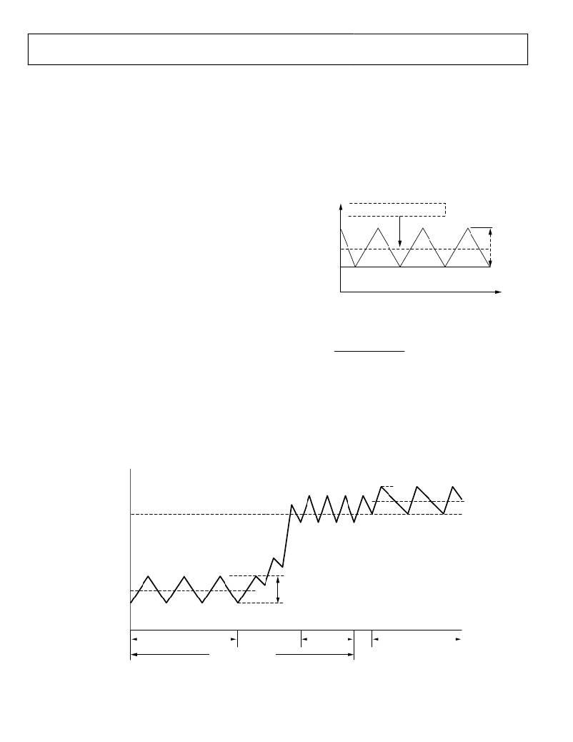
operation and during current limit. The output current, I OUT ,
The ripple current is calculated using Equation 6.
is the average of the inductor ripple current waveform. The
low-to-medium load current waveform illustrates the continuous
conduction mode operation with peak and valley inductor
Δ I L =
V OUT × ( V IN ? V OUT )
V IN × f SW × L
(6)
currents below the current limit threshold. When the load
current is increased, the ripple waveform maintains the same
amplitude and frequency because the current falls below the
current limit threshold at the valley of the ripple waveform.
As the current falls below the threshold during the normal off-
The ADP2102 also provides a negative current limit to prevent
an excessive reverse inductor current when the switching section
sinks current from the load in forced continuous conduction
mode. Under negative current limit conditions, both the high-
side and low-side switches are disabled.
time of each cycle, the start of each on-time is not delayed, and
the circuit output voltage is regulated at the correct value.
I PEAK
I OCL
CURRENT LIMIT
THRESHOLD
I VALLEY
INDUCTOR
CURRENT
I OUT
Δ I
MEDIUM LOAD
CURRENT
HIGH LOAD
CURRENT
CURRENT LIMIT
NORMAL OPERATION
Figure 45. Inductor Current—Current Limit Operation
Rev. B | Page 14 of 24
发布紧急采购,3分钟左右您将得到回复。
相关PDF资料
195D475X9020X2T
CAP TANT 4.7UF 20V 10% 2910
ADP2102-1.375EVALZ
BOARD EVAL FOR ADP2102-1.375
A9CCA-0604E
FLEX CABLE - AFK06A/AE06/AFK06A
R1S-1512/P-R
CONV DC/DC 1W 15VIN 12VOUT
195D475X0025X2T
CAP TANT 4.7UF 25V 20% 2910
195D475X0020X2T
CAP TANT 4.7UF 20V 20% 2910
195D336X9004X2T
CAP TANT 33UF 4V 10% 2910
195D336X0004X2T
CAP TANT 33UF 4V 20% 2910
相关代理商/技术参数
ADP2102-1.875EVALZ
功能描述:BOARD EVAL FOR ADP2102-1.875 RoHS:是 类别:编程器,开发系统 >> 评估板 - DC/DC 与 AC/DC(离线)SMPS 系列:- 产品培训模块:Obsolescence Mitigation Program 标准包装:1 系列:True Shutdown™ 主要目的:DC/DC,步升 输出及类型:1,非隔离 功率 - 输出:- 输出电压:- 电流 - 输出:1A 输入电压:2.5 V ~ 5.5 V 稳压器拓扑结构:升压 频率 - 开关:3MHz 板类型:完全填充 已供物品:板 已用 IC / 零件:MAX8969
ADP2102-1.8-EVALZ
功能描述:BOARD EVAL FOR ADP2102-1.8 RoHS:是 类别:编程器,开发系统 >> 评估板 - DC/DC 与 AC/DC(离线)SMPS 系列:- 产品培训模块:Obsolescence Mitigation Program 标准包装:1 系列:True Shutdown™ 主要目的:DC/DC,步升 输出及类型:1,非隔离 功率 - 输出:- 输出电压:- 电流 - 输出:1A 输入电压:2.5 V ~ 5.5 V 稳压器拓扑结构:升压 频率 - 开关:3MHz 板类型:完全填充 已供物品:板 已用 IC / 零件:MAX8969
ADP2102-1-EVALZ
功能描述:BOARD EVAL 0.8V-1.2V ADJ OUTPUT RoHS:是 类别:编程器,开发系统 >> 评估板 - DC/DC 与 AC/DC(离线)SMPS 系列:- 产品培训模块:Obsolescence Mitigation Program 标准包装:1 系列:True Shutdown™ 主要目的:DC/DC,步升 输出及类型:1,非隔离 功率 - 输出:- 输出电压:- 电流 - 输出:1A 输入电压:2.5 V ~ 5.5 V 稳压器拓扑结构:升压 频率 - 开关:3MHz 板类型:完全填充 已供物品:板 已用 IC / 零件:MAX8969
ADP2102-2-EVALZ
功能描述:BOARD EVAL 1.2V-1.5V ADJ OUTPUT RoHS:是 类别:编程器,开发系统 >> 评估板 - DC/DC 与 AC/DC(离线)SMPS 系列:- 产品培训模块:Obsolescence Mitigation Program 标准包装:1 系列:True Shutdown™ 主要目的:DC/DC,步升 输出及类型:1,非隔离 功率 - 输出:- 输出电压:- 电流 - 输出:1A 输入电压:2.5 V ~ 5.5 V 稳压器拓扑结构:升压 频率 - 开关:3MHz 板类型:完全填充 已供物品:板 已用 IC / 零件:MAX8969
ADP2102-3-EVALZ
功能描述:BOARD EVAL 1.5V-1.875V ADJ OUTPT RoHS:是 类别:编程器,开发系统 >> 评估板 - DC/DC 与 AC/DC(离线)SMPS 系列:- 产品培训模块:Obsolescence Mitigation Program 标准包装:1 系列:True Shutdown™ 主要目的:DC/DC,步升 输出及类型:1,非隔离 功率 - 输出:- 输出电压:- 电流 - 输出:1A 输入电压:2.5 V ~ 5.5 V 稳压器拓扑结构:升压 频率 - 开关:3MHz 板类型:完全填充 已供物品:板 已用 IC / 零件:MAX8969
ADP2102-4-EVALZ
功能描述:BOARD EVAL 2.5V-3.3V ADJ OUTPUT RoHS:是 类别:编程器,开发系统 >> 评估板 - DC/DC 与 AC/DC(离线)SMPS 系列:- 产品培训模块:Obsolescence Mitigation Program 标准包装:1 系列:True Shutdown™ 主要目的:DC/DC,步升 输出及类型:1,非隔离 功率 - 输出:- 输出电压:- 电流 - 输出:1A 输入电压:2.5 V ~ 5.5 V 稳压器拓扑结构:升压 频率 - 开关:3MHz 板类型:完全填充 已供物品:板 已用 IC / 零件:MAX8969
ADP2102A-EVALZ
制造商:Analog Devices 功能描述:ADJ OUTPUT FROM 0.8V-1.2V - Bulk
ADP2102B-EVALZ
制造商:Analog Devices 功能描述:ADJ OUTPUT FROM 1.2V-1.5V - Bulk
